
Designing an activated carbon treatment system can be complicated. There are many factors to consider when designing the system, including what type of water you need to treat, how much flow of water is coming in per day, and the size of your tank. Designing a granular activated carbon treatment system can also be difficult because there are so many different types of systems and configurations available today.
Table of Contents
Granular Activated Carbon
The versatility of carbon adsorption is unparalleled. For many applications, it has proven to be the least expensive treatment option and can remove a wide variety of organic compounds from waste water – including PFAS. One of its most desirable attributes is that GAC can remove contaminants to below detection limits. This is especially important in potable water treatment. Many bottled water producers use granular activated carbon to remove taste, odor, and contaminants from their product.
Adsorption is the process where an organic molecule comes into contact with activated carbon and is retained by physical or chemical forces. The physical forces at work in adsorption are the Van der Waals bonds.
Adsorption rules of thumb
Factors that affect the adsorption of a particular compound are:
- The adsorptivity of a substance increases as its solubility decreases.
- The adsorptive capacity of the water may be influenced by its pH.
- More so than aliphatic chemicals, aromatic and halogenated chemicals often bind well.
- Adsorption capacity decreases as temperature rises, although adsorption rate may increase.
- The surface characteristics of the adsorbent have a significant impact on adsorption capacity and speed. The material’s capacity is determined by the method used to activate the carbon.
- Contaminants such as the presence of variable amounts of pollutants, which might impact GAC efficiency, can be identified. Isotherms for single components may not be appropriate for mixtures.
- High suspended solids (50 mg/L or higher) and oil and grease (10 mg/L or higher) in streams can foul the carbon, requiring frequent media replacement. In most cases, pretreatment is usually required.
- Carbon is more expensive than other methods because it is the most costly treatment at sites with high COC concentrations. Activated carbon, on the other hand, may still be the lowest-cost choice depending on the type of COC used.
- Small molecules, such as ethanol, and highly soluble chemicals are not adsorbed as effectively as larger, less soluble compounds.
- Adsorbency increases with the size of the molecules.
- Non-polar chemicals bind more readily than polar substances.
Adsorption process in a fixed-bed vessel
When activated carbon particles are placed in water containing organic chemicals and mixed to give adequate contact, adsorption of the molecules occurs. The concentration will decrease from an initial value Co towards a new equilibrium point Ce where it has been measured that approximately 5 pounds per acre can be stored for up to two years before being released back into our environment. It is often feasible to discover a correlation between the equilibrium concentration and the quantity of organics adsorbed per unit mass of activated carbon by running a series of adsorption studies.
As a polluted water stream passes through a confined bed of activated carbon, a mass transfer zone forms. The carbon bed depth that is required to reduce the contaminant concentration from the start to end concentration at a given flow rate is known as the “mass transfer zone.”
As the mass transport zone passes through a carbon bed and approaches the end surface, concentrations of COCs begin to appear in the effluent. The breakthrough capacity of a substance is the maximum amount of material that can be adsorbed by bulk adsorption. This condition is referred to as “breakthrough,” and the quantity of material absorbed is measured. If the bed is left exposed to the water stream, the mass transfer zone will go all the way through it and the effluent contamination level will be identical to that of the influent. At that point, saturation capacity is reached. The saturated capacity is that which is represented by the isotherm.
Several carbon beds are often operated in series to take comprehensive advantage of the adsorption difference between breakthrough and saturation. The mass transfer zone may then move through the first bed completely before being removed from service. The effluent quality is maintained by the following beds in the series.
It’s critical that the bed depth be adequate to entirely encompass the mass transfer zone within the vessel. Typically, a bed depth of 1.2 to 1.8 meters (4 to 6 feet) is adequate for petroleum hydrocarbons. A permit requires that at least two carbon units be connected in series. To achieve the highest carbon efficiency, it is advised that you utilize three units in series.
Contaminants that carbon can treat
Activated carbon is effective at treating a wide range of contaminants.
Here is a partial list of compounds that are removed by activated carbon adsorption:
- Volatile organic compounds (VOCs)
- Fuel oil
- Solvents
- Polychlorinated biphenyls (PCBs)
- Dioxins
- PFAS
- Chlorine
- Lead
- Fluoride
- Pesticides
Raw material
Activated carbon is made from organic raw materials. Common materials used to make activated carbon include:
- coconut shells
- wood
- coal
- peat
- rice hulls
These base materials are pyrolyzed to drive off the water, hydrogen, and volatile material in the feedstock. The remaining material is called char. The char is activated with high temperature steam to produce pores.
Physical Properties of Activated Carbon
1 – Pores
Activated carbon has a large surface area because of its numerous very tiny pores. Typical activated carbons have surface areas ranging from 600 to 1,200 square meters per gram of carbon (m2/g) [3 x 10⁶ to 6 x 10⁶ square feet per pound of carbon (ft2/lb)], with some reported as high as 3,000 m2/g [1.5 x 107 ft2/lb]. The internal pores of the leaf are divided into two categories: micropores and macropores. (10 to 1,000 Å) or macropores (greater than 1,000 Å). The micropores absorb most of the petroleum hydrocarbons, while the macropores serve as pathways.
The kinetics of adsorption are significantly influenced by the size of the carbon particles. Rates of adsorption increase with a decrease in particle size. Smaller carbon particles have a greater adsorptive capacity than larger ones. In other words, the flow rate is related to head loss and inversely proportionate to the average size of carbon particles.
This relationship is defined by the following equation:
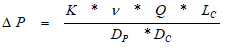
ΔP = Pressure drop
K = constant
ν = viscosity
Q = flow rate
Lc = Carbon bed depth
Dp = Mean particle diameter
Dc = Column diameter
All grades of carbon are represented by pressure loss curves from the majority of carbon suppliers. Typically, these curves show the pressure drop per unit depth of carbon versus the superficial speed of the liquid flow.
When designing an adsorber, a balance must be found between the perfect particle size for adsorption and the maximum acceptable head loss. In potable treatment applications, it is generally advantageous to utilize the smallest available granular activated carbon, which provides optimum adsorption capacity, and address the increased pressure loss by using pressure-rated carbon vessels and pumps with higher head capacity.
2 – Iodine and Molasses Number
The iodine number indicates the amount of tiny pores in a given carbon. It is defined as the milligrams of iodine (I2) that are adsorbed per gram of carbon when the equilibrium concentration of the bulk saturation (Ceq) is 0.02 normal. It is also correlated with the surface area in pores with diameters within the range of 10 to 28 Å. The capacity of a carbon to adsorb smaller molecules is indicated by the concentration of iodine.
The molasses number, on the other hand, refers to the number of large pores within a given carbon. The ratio of the optical densities of a molasses solution treated with a specified activated carbon and one treated with the evaluated activated carbon is used to compute it. The molasses number can be correlated with the surface area in pores with diameters greater than 28 Å. Because the color pigments in molasses are big molecules, this data suggests which carbon can adsorb bigger chemicals.
For non-published isotherms, the iodine and molasses numbers can be used as a relative measure (not an adsorption rate) for determining the equilibrium adsorption capacity of a carbon for small and large adsorbate molecules.
3 – Apparent Density
The solid or skeletal density of most activated carbons is about 125 to 130 pounds per cubic foot [lb/ft3]. A more practical parameter is the apparent density or mass of a given volume of adsorbent particle. The density is significantly lower than the solid density due to the presence of pores within the particles and void space between particles. In most commercial GACs, the apparent density is between 25 to 31 lb/ft3.
4 – Particle Size
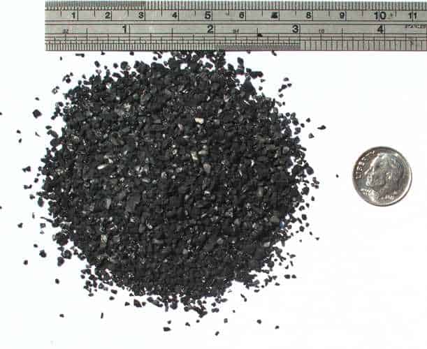
The size of the GAC is determined by the U.S. Sieve range, which will cover the majority of particles in a spectrum of sizes. Typically, the range is specified to cover 85 to 90 percent of the whole product, with a few percent more or less permitted by requirement. The numbers represent the openings per inch of a specific size. A 4 x 10 mesh product, for example, is one that is small enough to pass through a #4 sieve and large enough to be retained on a #10 sieve. A similar approach is occasionally used with the Tyler Screen or other screen sizes.
5 – Corrosion
Granular activated carbon is chemically conducting and can create a galvanic cell, which then corrodes carbon steel. The materials of construction must be chosen with regard to the fluid’s corrosiveness and regeneration method. To prevent corrosion and early vessel failure, steel vessels should be epoxy or polyurethane coated. If polymers or rubber are present in vessel materials, internal components (such as distributors, piping, and screens), or access seals (manways, etc.), material compatibility with the VOCs should be tested.
Liquid-Phase GAC Design Considerations
GAC is a common and effective treatment approach that works well in a liquid phase applicaton. It is considered a best available control technology (BACT) by many regulatory agencies and is a benchmark for other remediation technologies. It is critical to the success of carbon adsorption that the final design optimize and balance the hydraulic performance of the GAC and vessel with the dynamic adsorption process. The following sections present these parameters and methods for optimizing them.
1 – Minimum carbon bed mass
The carbon bed must have a sufficient amount of mass to remove the pollutants contained in the liquid flow for an adequate length of time. The minimum duration of carbon bed life (i.e., the time before breakthrough occurs) is site-specific, but it should be at least 30 days and ideally 90 days.
Carbon bed life will be shorter during system startup since the initial COC levels are higher. Longer periods of service are more appealing because they cut down on carbon replacement events and the risk of a discharge exceedance. A fixed-bed system, on the other hand, will require higher carbon mass in order to duplicate the same amount of growth as a vat. Therefore, a compromise between maximum bed life and the capital investment required must be achieved.
The life of a GAC is determined by a variety of variables, the most significant of which being the contaminants’ mass rate. The mass rate of contaminants may be calculated as shown below:
Mass Flow Rate = Flow * Concentration
where,
Flow = volumetric flow rate
Concentration = milligrams per liter (mg/L)
The detection of pollutants in the effluent is known as a breakthrough. This usually happens when the carbon bed’s adsorption capacity has been utilized. An equilibrium saturation is the maximum amount of a certain contaminant that can be removed from a waste stream by an activated carbon when it is in its ideal operating state. It represents the quantity of a given compound adsorbed per unit weight of activated carbon from a fluid mixture at equilibrium temperature and concentration.
Equilibrium saturation may be determined from the following equation:
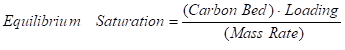
where,
Equilibrium Saturation = time until breakthrough (days)
Carbon Bed = mass of carbon in vessel (kg) or (lb)
Loading = GAC adsorption capacity (kg organic/kg GAC) or
(lb organic/lb GAC)
Mass Rate = mass rate of contaminants (kg/day) or (lb/day)
To allow for continued operation for a long period of time, a well-designed GAC vessel should have enough contaminant mass removal capacity to last until the carbon bed is replaced. Between carbon changes, most systems are designed to last at least 90 days. However, many variables must be taken into account while selecting the minimum carbon bed mass, such as travel time to and from the site, operation and maintenance spending, site limitations, equipment shed space restrictions, potential environmental impacts if a discharge is violated, and other concerns.
The minimum carbon bed size can be determined for a given system and the desired bed life by rearranging the above equation as follows:

Loading is a dynamic process and will vary as a function of many variables including the pore size distribution of the carbon, the molecular size and concentration of the contaminants, flow rate, compound solubility in water, and the presence of competing compounds. The adsorption isotherm is used to predict the performance of activated carbon. The isotherm is a statistic that quantifies the quantity of soluble organic adsorbed per unit weight of carbon at various concentrations at constant temperature. The data collected from batch tests is plotted on a log-log graph to form a straight line fit based on the empirical Freundlich equation:
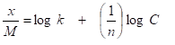
where,
x = amount of contaminant adsorbed (mg) or (lb)
M = weight of carbon (g) or (lb)
k = constant
n = constant
C = equilibrium concentration in solution after desorption (mg/L)
Isotherms are only available for pure compounds, and they do not take into account the adsorption dynamics of numerous substances. Carbon adsorption is difficult to do and not reliable as a result. However, in order to compare systems, total loading can be calculated using pure compound isotherms.
The volume of carbon required to provide the minimum carbon life can be determined with the following equation:
where,
Volume = minimum carbon volume required (m3) of (ft3)
BD = bulk density (kg/m3) or (lb/ft3)
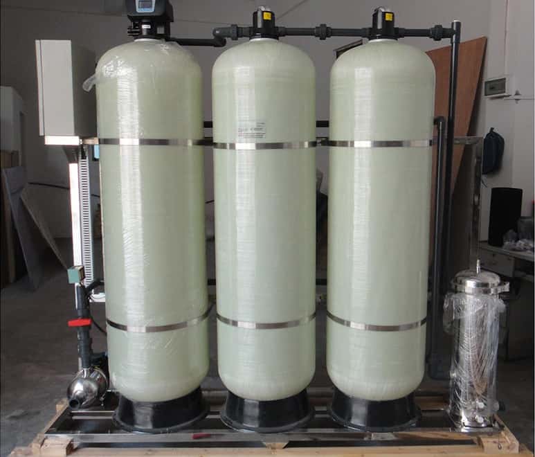
2 – Vessel flow configuration
Downflow, upflow, fixed-bed, and fluidized-bed adsorption vessel flow configurations are all available. Upflow designs are more popular for smaller flows. The downflow, fixed-bed cell is ideal for potable water treatment and is the most popular and commonplace design.
Pre-engineered carbon vessels are most often (and usually only) offered in downflow design. The water enters the top of the vessel, is evenly dispersed across the carbon bed by the packed bed design, and is collected by slotted screens at the bottom of the device. The liquid goes through the carbon until it is spent, or the effluent limit is reached. The adsorber is then purged of the entire volume of carbon, and virgin or re-activated carbon is put in the vessel.
The goal of the underdrain system is to keep a consistent flow pattern so that channeling is avoided and all carbon is utilized to the maximum extent possible. The underdrain laterals must be made of materials that are compatible with the pollutants and water chemistry, as well as having slots designed to retain 100 percent of the carbon necessary to maintain the specified flow rate. This underdrain must be designed so that water is collected evenly, such that the mass transfer zone is drawn down in an even, or plug flow, manner to get full value from the installed carbon. Backwash water may also be introduced into the underdrain, allowing for even water distribution over the entire bed cross section.
Many types of adsorption vessels are available for use in a variety of applications. These include pressure and gravity-fed systems, as well as those that utilize different media such as sand or chemicals with metal ions attached to them (GAC).
Carbon vessels can be arranged in various ways including the following:
- single vessel
- two or more vessels in series
- two or more vessels in parallel
- four or more vessels in series-parallel
The most efficient arrangement for polishing is two or more vessels in series. This allows the first, primary carbon unit to remain active until its bed becomes completely saturated. Once spent, the carbon in the primary unit is replaced and the flow direction is reversed. This allows the fresh carbon to be used a polishing to maximize the bed life and the overall efficiency.
For groundwater treatment applications, the recommended design elements of a liquid-phase carbon adsorption vessels are:
- Downflow (top to bottom) configuration
- Pressure-rated vessel
- Two or more vessels in series
- A minimum 20% freeboard to allow sufficient volume in the carbon vessel for backwashing
3 – Hydraulic considerations
The Plug Flow Theory suggests that a contaminant will move through an adsorptive vessel in plugs or waves. The leading edge of these “plugs” contains the area where absorption takes place, withstanding until more carbon is available ahead for loading up on any potential toxins before they’re able to diffuse outwards from this central region as opposed to just flowing continuously throughout all areas without stopping at different points along its length like water would do if there was no barrier between it and whatever surface you spilled onto from above.
The surface loading rate, often known as the hydraulic loading rate, is the pace at which a “plug” of water travels through an empty GAC contactor vessel when it’s empty. It is defined as:
Although this term can also be expressed in units of velocity, it is generally expressed in the more convenient units of hydraulic loading such as gallons per minute per square foot [gpm/ft2].
Empirical evidence shows that the optimum hydraulic loading for petroleum hydrocarbons is between 2 and 7 gpm/ft2. When this number falls below 1 or rises above 9, channeling of water may occur due to reduced contact time with GAC which reduces its effectiveness at adsorbing contaminants. Conversely, when it reaches 8 or more, an excess amount will flow through channels in order to reduce backpressure on either side making these areas ineffective at adsorbing contaminants.
For a specific flow rate and the minimum hydraulic loading rate, the necessary vessel geometry can be calculated to provide optimum carbon usage. The following equation can be used to determine the carbon vessel radius:
where,
Rmin = minimum vessel radius
Flow = flow rate
Loadingmax = maximum surface loading rate of the carbon media
The maximum surface loading rate is used to determine the minimum required vessel radius, and then the nearest commercially available unit is chosen.
The empty bed contact time (EBCT) is the theoretical time during which a single fluid particle remains in contact with the carbon bed. It is defined by:
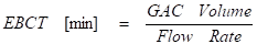
For a given flow rate, vessel radius, and minimum EBCT, the necessary vessel geometry can be determined to ensure continuous system operation while conserving carbon. The following equation can be used to determine the required carbon vessel sidewall height:
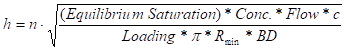
where,
h = vessel sidewall height
n = number of vessels in series flow arrangement
Rmin = minimum vessel radius
c = constant
In general,
- 10 to 15 minutes (EBCT) is usually sufficient for the treatment of petroleum hydrocarbon-contaminated groundwater
- the frequency of carbon replacement increases as the EBCT decreases, and the bed life decreases
- yo achieve a finished product with less residual solvent, larger contact times may be required for organic compounds with low adsorption rates
General guidelines for sizing GAC vessels to treat petrochemical pollutants if the effluent discharge limit proportion to the influent VOC concentration is high are as follows. (Ceff/Cinf > 0.3) are as follows:
- The minimum EBCT is 10 to 15 minutes
- Hydraulic loading rates of 3 to 7 gpm/ft2 are required
- Add one additional carbon unit, plumbed in sequence, to the total number of vessels required to fulfill the discharge criteria. If two vessels plumbed in series satisfy the discharge requirements, a third vessel plumbed in series should be included
If the effluent discharge limit is only a small percentage of the influent VOC concentration, (Ceff/Cinf < 0.05), the following rules of thumb should be utilized:
- The minimum EBCT ranges from 20 to 30 minutes
- Hydraulic loading rates of 3 to 5 gpm/ft2 are required
- Add two more carbon units, in series, to the number of vessels needed to fulfill the discharge criteria. For example, if the discharge requirements of two vessels plumbed in series could be satisfied by a third and fourth vessel plumbed in series, a third and fourth vessel plumbed in series should be used
Wrap Up Liquid Phase GAC Design
Carbon adsorption is an extremely good treatment technology. It is the least expensive way to treat water for many applications. Adsorption is also good at removing low concentrations of waste and it meets strict requirements for treatment levels. One of the major things about activated carbon is that it can remove a wide variety of organic compounds, including ones that are difficult to clean up, to levels below what can be detected.